


Over the years, computational fluid dynamics (CFD) software has simplified the prepping and meshing of fluid models — making CFD technology more accessible to the general engineering community.
Here are three best practices for simulating fluid models.
1. Use Geometry Wrapping to Create Watertight Fluid Models
The geometry that designers send to engineers is rarely clean enough to import into a fluids model. Fixing these gaps and leaks in the geometry can traditionally take hours, even days.
Therefore, engineers should use a CFD software that can wrap a surface mesh around discontinuous geometry. This meshing capability will quickly fill in all the gaps, leaving more time for simulation and results generation.
For example, fault-tolerant workflow for non-watertight geometries can create that surface mesh wrapper.
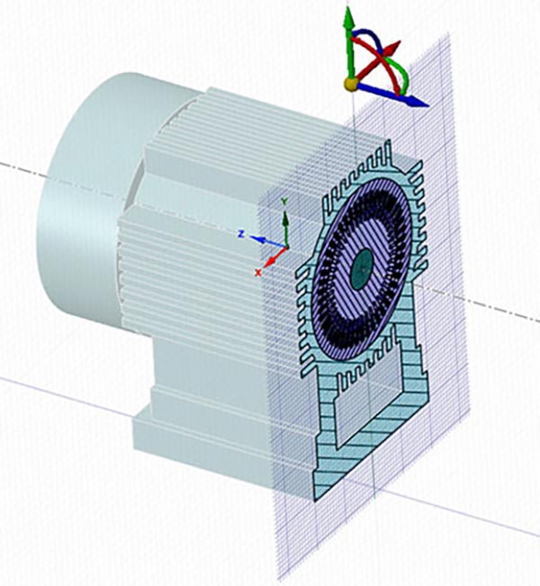
2. Combine Overlapping Geometry to Quickly Create a Flow Boundary
Engineers can create a flow boundary by wrapping a box around watertight geometry and combining all the overlapping faces between the solids into one face.
This will resolve the intersections between the box and source geometry. The volume can then be extracted and imported into a fluids model.
Engineers can use the “share topology” function to create the flow geometry using ANSYS SpaceClaim. With Fluent’s “surface mesh” operation, they can extract the flow volume from the void between the boundaries in the geometry.
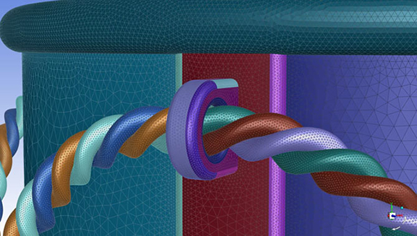
3. Conformally Connect Meshes Together to Avoid Gaps
Engineers can reduce computational times by creating fluids models with coarse meshes for large areas and fine meshes near detailed geometry. The challenge then becomes linking these disparate meshes together without gaps.
Linking meshes is a tedious job. It typically requires cleaning up the geometry and manually correcting the meshes so everything fits nicely together.
ANSYS Fluent’s Mosaic-enabled meshing technology can automatically link these grids using a poly-hexcore mesh. Any type of mesh can be connected using this technology, including:
- Tetrahedral meshes
- Hexcore meshes
- Polyhedral meshes
- Poly-hexcore meshes
For more information about the ANSYS product range, please click here >>
This blog was originally posted on ANSYS’ website .

